Hints and tips for servicing panels
The following sections of this page is where I pin various notes and reminders about panels I work with. Such as how to test without sounders and relays etc. As well as other notes that may assist in service work or installing additional equipment.
Ziton ZP2 Locating devices
Select Locate device to activate a loop device LED. This helps to identify the
location of a device in the installation. You will need the Firenet ID of any remote
device LED to be activated.
To locate a device:
1. Select Test from the Main menu, and then select Locate device.
2. Select the loop number, All loops, or Remote (if Remote is selected, enter the
Firenet ID, loop number, and device address when prompted).
A list of all the devices on the selected loops is displayed.
3. Select the corresponding device, and then press the jog dial to activate the
device LED. To turn off the device LED, press the jog dial again.
4. Press F2 (Exit) to exit the menu.
Ziton ZP2 Test Zones
1. Select Test from the Main menu.
2. Select Zones.
3. Select the zone to test, and then press the jog dial to start the test. Press the
jog dial again to end the test for the selected zone.
By default you can select and test up to a maximum of four zones to test at
the same time (the maximum number of zones in test is configurable).
4. Press F2 (Exit) to exit the menu.
Repeat the above steps to end the zone test.
When an alarm is activated in a zone in test:
• The zone test is confirmed on the LCD while the alarm is active
• If a zone board is installed and the corresponding zone is included on the
zone board, then the zone alarm LED is flashing or steady (depending on the
source of the alarm)
• Fire routing, fire protection, sounders, and programmable activations are not
activated
• The control panel resets the initiating device after 5 seconds and clears the
alarm (manual call points must first be closed before an automatic reset can
be applied)
• The event is recorded in the event log
When there is a fire alarm in any zone that is not in test, the control panel
responds to the alarm event as configured.
Ziton ZP2 Service Mode
Activating service mode
Select Activate service mode to avoid accidental activation or deactivation of
outputs or output groups (local or remote) during tests.
In this mode the control panel indicates and logs activation events as configured
but does not activate or deactivate the corresponding output. This can be used to
verify control panel event configuration and to verify that outputs are not
activated accidentally.
To activate service mode:
1. Select Test from the Main menu, and then select Service mode.
2. Select Activate service mode, and then select YES (to activate service mode)
or NO (to deactivate service mode).
3. Select Global, and then select YES (to activate service mode across the
network) or NO (for local testing only).
4. Press F2 (Exit) to exit the menu.
Remember to exit service mode when all tests are completed.
Ziton ZP1 fire routing disablement and enablement
Disabling or enabling fire routing
To disable fire routing, press the General Disable button, and then press the Fire Routing Start button.
The disablement is indicated as follows:
• A steady General Disable LED
• A steady yellow Fire Routing On LED
To enable fire routing, press the General Disable button, and then press the Fire Routing On button again.
Note: Disabled fire routing does not operate or indicate a fault if there is a fire alarm.
Haes EN
I was asked to examine 2 existing door closers for part numbers. It turned out that what was actually wanted was the installation of 2 door retainers. The retainers will need a power supply with battery backup and the power supply will need a separate mains feed run from the electrical intake room.
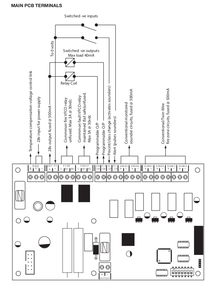
The siganl to operate this will be from the Heas panel.
All 12 zones are in use and a fire relay is already install and is using the 28V supply.
Fortunately according to the manual it seems that it is possible to program any of the other outputs to switch the ground when a fire condition occurs. This switching can be set to open, closed or pulsing.


